
I/O Programming -- Interfacing of LED and Switch
Procedure
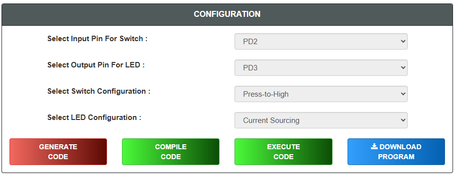
Configuration
- Select Input Pin For Switch
- Select Output Pin For LED
- Select Switch Configuration
- Select LED Configuration
- Click on "GENERATE CODE" button to generate code
- Click on "COMPILE" button to compile code
- Click on "EXECUTE" button to execute code and goto mimic
- If you want to download code click on "DOWNLOAD" button
- The MIMIC will open on left side of screen
Simulation
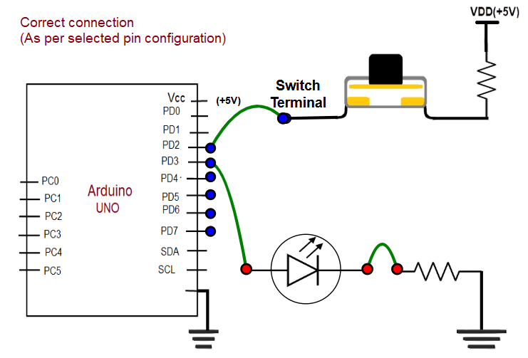
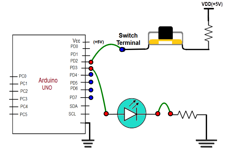
- Connect the Output Pin to the Anode
- Click on the cathode terminal and then click on the resistor terminal to connect the cathode with the resistor or vice versa
- Click on the selected input pin terminal and then click on the switch terminal to connect the input pin with the switch terminal or vice versa
- Click on the "Check Connection" button
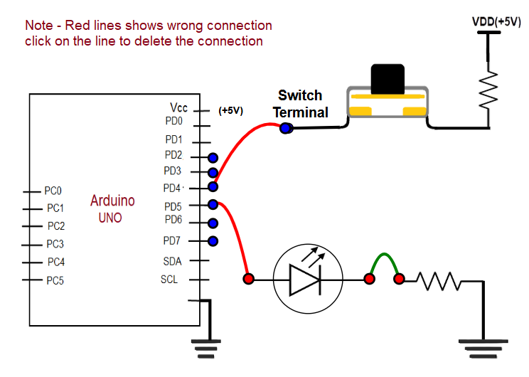
If connection is wrong, click on "Reset Connection" button and follow steps 1, 2, 3, and 4 again or click on red lines to delete the connection
If connection is successful, click on Switch available on the screen with black color and hold the switch for a few seconds
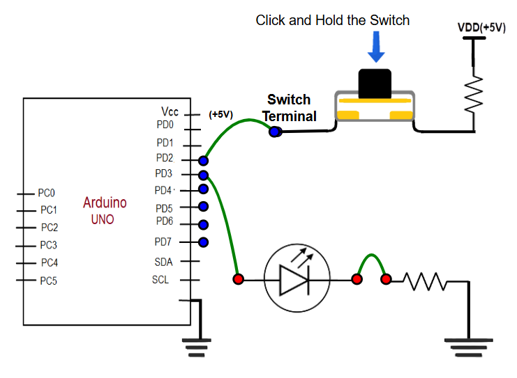
While holding the switch, Output LED is on. Observe the square wave graph to see how the output changes until you complete the observation
Click on "NEXT LEVEL" button go to next stage
Questions
- Read all the questions carefully and submit the answer
- After submission, verify the answers
- Click on result button, "Result" page will displayed